Push pull refrigerant recovery diagram – Introducing the push-pull refrigerant recovery diagram, a vital tool for understanding and executing refrigerant recovery procedures. This diagram serves as a roadmap, guiding technicians through the intricate steps of refrigerant recovery, ensuring safety and efficiency. Embark on this informative journey to master the intricacies of push-pull refrigerant recovery.
Refrigerant recovery is a crucial process in refrigeration and air conditioning systems, safeguarding the environment and upholding system performance. The push-pull method stands out as a reliable and widely adopted technique for refrigerant recovery, offering advantages over other methods. This guide will delve into the details of the push-pull refrigerant recovery diagram, empowering technicians with the knowledge to operate these systems effectively.
Refrigeration Cycle: Push Pull Refrigerant Recovery Diagram

The refrigeration cycle is a thermodynamic process that uses a refrigerant to remove heat from a cold source and transfer it to a hot source. The refrigerant undergoes four main processes: compression, condensation, expansion, and evaporation.
Compression:The refrigerant is compressed by a compressor, which increases its pressure and temperature. This process requires energy input.
Condensation:The compressed refrigerant flows through a condenser, where it releases heat to the surrounding environment and condenses into a liquid. This process occurs at a constant pressure.
Expansion:The liquid refrigerant flows through an expansion valve, which reduces its pressure and temperature. This process results in the formation of a two-phase mixture of liquid and vapor.
Evaporation:The two-phase mixture flows through an evaporator, where it absorbs heat from the cold source and evaporates into a vapor. This process occurs at a constant pressure.
Refrigerant Recovery
Refrigerant recovery is the process of removing refrigerant from a refrigeration system. It is important to recover refrigerant because it is a greenhouse gas that contributes to climate change. There are two main methods of refrigerant recovery: push-pull and vacuum recovery.
- Push-pull recovery:This method uses a recovery machine to create a pressure difference between the refrigeration system and the recovery cylinder. The refrigerant is pushed out of the system and into the recovery cylinder.
- Vacuum recovery:This method uses a vacuum pump to create a vacuum in the recovery cylinder. The refrigerant is drawn out of the system and into the recovery cylinder.
Push-Pull Refrigerant Recovery Diagram
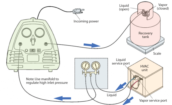
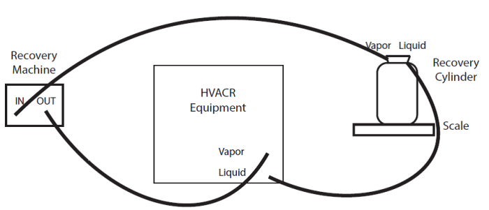
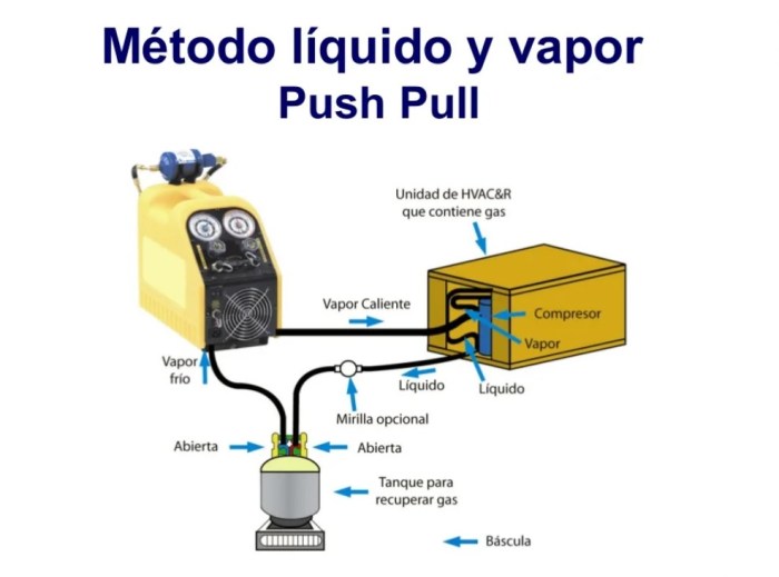
A push-pull refrigerant recovery system consists of the following major components:
- Recovery cylinder
- Refrigerant hoses
- Recovery machine
The recovery process involves the following steps:
- Connect the recovery hoses to the refrigeration system and the recovery cylinder.
- Start the recovery machine.
- Monitor the pressure gauges on the recovery machine to ensure that the refrigerant is being recovered properly.
- Once the refrigerant has been recovered, turn off the recovery machine and disconnect the hoses.
Safety Precautions
There are several potential hazards associated with refrigerant recovery, including:
- Exposure to refrigerant
- Fire
- Explosion
To avoid these hazards, it is important to take the following safety precautions:
- Wear appropriate personal protective equipment (PPE), including gloves, safety glasses, and a respirator.
- Use proper ventilation to ensure that the area where the refrigerant is being recovered is well-ventilated.
- Follow the manufacturer’s instructions for the recovery machine.
Troubleshooting, Push pull refrigerant recovery diagram
There are several common problems that can occur during refrigerant recovery, including:
- The recovery machine is not working properly.
- The refrigerant is not being recovered from the system.
- The refrigerant is leaking from the system.
If you encounter any of these problems, you should troubleshoot the system to identify the cause of the problem and take the appropriate corrective action.
Frequently Asked Questions
What is the purpose of a push-pull refrigerant recovery diagram?
A push-pull refrigerant recovery diagram serves as a visual guide, providing a detailed representation of the system components and their interconnections. It assists technicians in understanding the process of refrigerant recovery, ensuring proper operation and safety.
What are the key components of a push-pull refrigerant recovery system?
The major components of a push-pull refrigerant recovery system include the recovery cylinder, refrigerant hoses, recovery machine, pressure gauges, and safety devices. Each component plays a specific role in the recovery process.
What safety precautions should be taken when using a push-pull refrigerant recovery system?
Technicians must wear appropriate personal protective equipment (PPE), including gloves, safety glasses, and respiratory protection. Proper ventilation is essential to prevent refrigerant exposure. Additionally, the system should be inspected for leaks before operation, and all connections must be secure.

